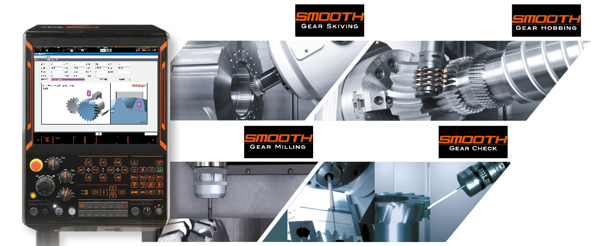
The integration of INTEGREX multi-tasking with gear cutting and measurement
| 5-axis machining | Gear machining | Gear measurement | ||
 |
+ |  |
+ |  |
|
|
|
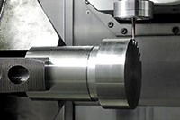
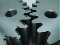
Perform a variety of gear cutting processes
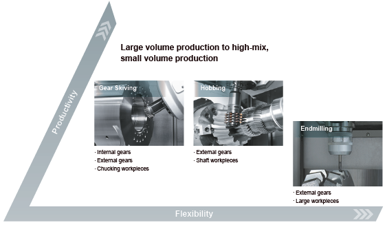

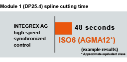
Improved productivity thanks to high-speed gear skiving
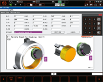
- High accuracy gear skiving is realized thanks to unique INTEGREX AG control technology
- Rotation of both the main spindle and the milling spindle is synchronized up to the top speed of both spindles to ensure high accuracy gear skiving.
Internal spline cutting applications - INTEGREX i-200ST AG
 Thanks to INTEGREX i-200ST AG synchronized control technology, productivity is 6 times higher when compared to conventional internal spline processing. Additionally, with higher speed operation cutting resistance is reduced for higher accuracy

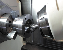
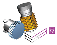
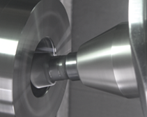
The hob arbor is held on one end by the heavy-duty milling spindle providing sufficient rigidity for high accuracy gear hobbing. With Smooth Gear Hobbing, gear specification data are input to automatically generate the tool path.
| Hob Shift | Modified gear lead and gear crowning | |
| This function shifts the contact point of the hob and workpiece to extend tool life. | By inputting data for a modified gear lead or gear crowning, the tool path for gear hobbing is automatically generated. | |
 |
 |

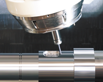
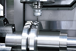 Using Smooth Gear Milling software, gear teeth can be cut one by one by a standard endmill. Gear specification data, including data for modified gears as well as modified gear lead and modified gear profile, are input to automatically generate the tool path.

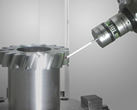
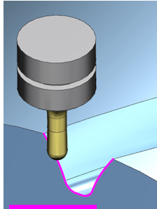
Once a gear has been machined, deburring of front and end edges can be performed with a standard ball-nosed endmill. In cases where the phase of the gear is unknown (such as after gear hobbing), Smooth gear measuring can be used to discover where the tooth gap is before the deburring process takes place.
 |
 |

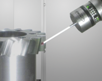
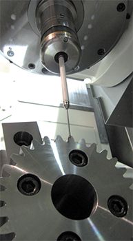 After using a new or reground tool, a gear tooth can be probed by a touch sensor to determine the required amount of compensation.